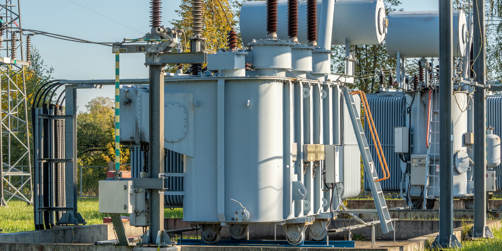
How Does a Transformer Work?
Transformers are one of the most important pieces of electrical equipment you’ll ever work with. They’re behind almost every power system — from the massive ones in substations to the little ones in phone chargers.
But how do they actually work? Let’s break it down in simple terms so it’s easy to explain to apprentices, clients, or anyone new to the trade.
Anatomy of a Transformer
A transformer has three main parts:
-
Primary Coil – This is where the input voltage (supply side) goes in.
-
Secondary Coil – This is where the output voltage (load side) comes out.
-
Iron Core – This concentrates the magnetic field and links the two coils magnetically.
There’s no direct electrical connection between the primary and secondary windings — only a magnetic one. That’s why transformers are so useful for isolating and stepping voltages up or down safely.
The Transformer Ratio
The voltage ratio between the two sides is directly related to the turns ratio of the coils:
V₁ / V₂ = N₁ / N₂
Where:
-
V₁ = Primary voltage
-
V₂ = Secondary voltage
-
N₁ = Number of turns in the primary winding
-
N₂ = Number of turns in the secondary winding
So, a transformer with 100 turns on the primary and 50 turns on the secondary will halve the voltage.
The Basic Principal: Electromagnetic Induction
At the heart of every transformer is a simple idea — changing magnetic fields can create electricity.
When alternating current (AC) flows through a wire, it produces a magnetic field that constantly changes direction. If another wire sits within that magnetic field, it will have a voltage induced into it.
That process is called electromagnetic induction, and it’s the foundation of how all transformers work.
Step by step process:
-
AC voltage is applied to the primary coil.
-
This creates a magnetic field in the iron core that expands and collapses as the AC alternates.
-
The changing magnetic field induces a voltage in the secondary coil.
-
The ratio of turns between the primary and secondary determines the new voltage level.
Note: So, if the secondary coil has fewer turns than the primary, the output voltage will be lower — that’s a step-down transformer.
If it has more turns, it’s a step-up transformer.
Types of Transformers and Their Uses
Step-Down Transformer
Reduces voltage (e.g. 230V to 24V control circuits, or from high-voltage transmission to distribution).
Step-Up Transformer
Increases voltage (e.g. generator to transmission systems).
Isolation Transformer
Keeps input and output electrically separate — used for safety and noise reduction.
Instrument Transformer
Used for measurement — includes Current Transformers (CTs) and Voltage Transformers (VTs).
Auto Transformer
Uses a single winding with a tapped section — compact and efficient, but not isolated. Used in motor starting and voltage regulation.
When fault-finding low-voltage control circuits, remember that many 24V or 12V systems are powered through step-down control transformers. A fault on the secondary side can still affect the breaker on the primary side — always isolate both before testing.

